by Dudley Boden and Paloma Domenico
NDT MARKETPLACE DECEMBER 2013
A new design has been developed for the ultrasonic testing (UT) of drawn over mandrel seamless carbon steel tube and pipe that enables manufacturers to test with fewer adjustments to accommodate varying diameters of material, without the need for time-consuming configuration changes. Not only is this design applicable to spin the tube, but it can inspect almost any round metal product during the manufacturing and production process and has already been installed as an ultrasonic tube and pipe end tester.
This configuration also allows for tapered and upset ends and meets various demanding industry specifications such as American Petroleum Institute standards API 5CT and API 5L (API, 2000; API, 2000). This particular system was designed to replace an electromagnetic acoustic transducer (EMAT) system that did not provide the level of test required; however, this mechanical configuration can be used with any type of sensor. It would be possible to put phased array UT sensors, EMAT sensors, or even eddy current sensors in this mechanical configuration just by changing the internal mounting for the particular sensor.
Examples of the flexibility this design provides include how the device was originally configured with one ultrasonic transducer test head to inspect tube ends. Another example is the one described in this paper: a dual transducer head assembly used for extremely large diameter pipe commonly applied to the oil and gas industry.

The Mechanics
This new mechanical design was implemented as an ultrasonic system and provided as a turnkey system. There are two electrical power connections along with compressed air. Everything else is completely integral to the system, including a programmable logic controller, ultrasonic signal cables, water package controls, and mechanical movement (both automatic and manual) of the test head. These features ensure seamless installation into the customer's test line, whether it is a new system or an upgrade of an older unit.
There are three main variables that need to be taken into account when inspecting a spinning tube.
- A fixed helical pitch must be established. In this example, the helical pitch remains constant at 76 mm (3 in.).
- Surface speed, also referred to as surface velocity or linear speed, must be determined. For this example, it is a fixed rate using a 356 mm (14 in.) diameter reference tube, which results in 2 m/s (6.6 ft/s) linear speed.
- Rotational speed or rotations per minute is diameter dependent: the larger the diameter, the less coverage of the tube per minute. In this instance, the range is from 9.1 to 36.6 m/min (30 to 120 ft/min).
As long as two of the three variables remain fixed, the third may be accurately calculated with variations.


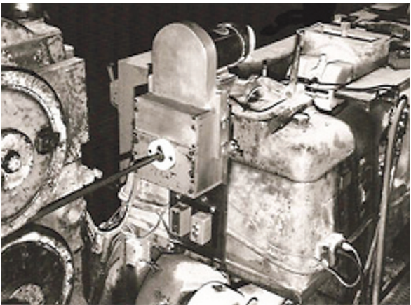
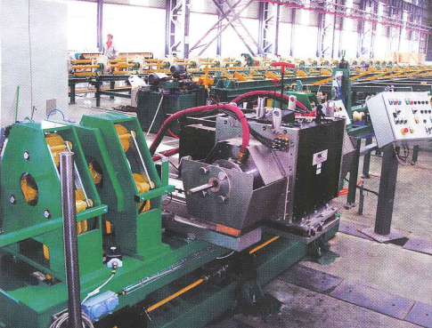
The system being used as the example (Figure 1) starts with a simple water tank—a key first advantage. Because this immersion system is under the pipe, a tank without tight fitting glands or shoes can be used. This results in lower water circulation requirements, fewer wear components, and few changes being required to the basic water tank during size changeover. Water is fed into the tank from below and maintained via a water recirculation and filtration system.
The second critical component is a means of ensuring that the tank and transducers are aligned properly with the pipe. In this system, because the material rides over the transducer heads without the constraint of a rotary system or top-mounted probes, alignment is accomplished using a unique set of rollers that automatically adjust to the helical pitch of the pipe to ensure proper tank positioning while minimizing the wear on the rollers. The rollers are part of the automatic pitch control (APC) carrier, which is lifted into the test position by an air cylinder. These rollers are adjusted very quickly to accommodate pipe size changes and are the main adjustment that needs to be made on size changeover.
With proper adjustment of the rollers via the diameter scale, no transducer adjustment is required. This produces the same distance from the transducers to the tube bottom so that all angles remain constant. If the wall-to-outer-diameter ratio is not too severe, no change is necessary to obtain a balanced setup. The air cylinder provides a flexible holding structure designed to follow material that is not straight. The test configuration also permits tapered and upset ends pass easily, and the APC rollers and transducer arrangement are designed to reduce untested ends.

Thirdly, the tank needs to be able to follow movement in the pipe caused by unstraightness. The combination of pinch rollers on the top of the pipe and an air cylinder that supports the tank provides a flexible mount that ensures proper positioning as the pipe moves around.
Complete coverage is provided with 12 longitudinal and 6 transverse elements in each transducer head, covering both clockwise and counter-clockwise directions. Independent angles for outer diameter and inner diameter on heavy wall tubes allow for accurate and consistent repeatability of discontinuity and thickness detection. Discontinuity detection down to 5% wall thickness is reliably achievable, meeting API 5CT and API 5L specifications (API, 2000; API, 2000).
Discontinuity detection is based on the user's reference standard. For these specifications, a reference standard consisted of 12.7 and 25.4 mm (0.5 and 1 in.) wide outer diameter and inner diameter transverse notches, as well as 12.7 and 25.4 mm (0.5 and 1 in.) long outer diameter and inner diameter longitudinal notches (as shown in Figure 2) based on tables C62-64 in API 5CT (API, 2000). A 6.4 mm (0.25 in.) longitudinal notch was used for a static sensitivity check.
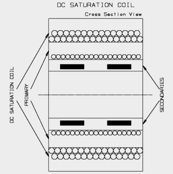
However, with this design approach, shown in Figure 3, the system can be very flexible. If fewer transducers are required, the system can be configured with only one tank or with more than two tanks for very complex testing.
The Electronics
The UT discontinuity electronics, shown in Figure 4, are provided along with the test head. Thirty-six channels of instrumentation are easily controlled by the operator. All of the calibration parameters can be saved and later recalled for quick operator setup. Features such as global control allow the operator to adjust multiple channels at once.
Specialized mapping features essentially multiplex all similar channels into a single recording trace for easy and intuitive viewing of all test signals.
The green signals in Figure 4 represent the outer diameter notches, while the white signals represent inner diameter notches. On the left side of this chart screen, each channel is labeled with its corresponding transducers (clockwise longitudinal, counter-clockwise longitudinal, wall thickness, transverse reverse, transverse forward, and lamination). On the bottom, pipe length, speed, and piece count are presented. Time, date, accept, and reject specifications are also given.


The operator control panel can be used in both automatic and manual mode, as shown in Figure 5. The auto mode provides fully automatic testing of pieces. Transducer heads and pressure rollers are controlled by the optical proxy switches when a tube passes. In manual mode, transducer heads and pressure rollers are controlled by the operator. This mode is used to set up the ultrasonic electronics on a test standard.
Conclusion
There are many alternatives regarding nondestructive testing of carbon steel for small and medium diameter pipe up to approximately 178 or 203 mm (7 or 8 in.) in diameter. Depending on the end use and characteristics of the pipe, eddy current encircling coil or weld-only tangent coil inspection is very common. In some cases, even rotary eddy current testing is done. However, for a large number of applications where the wall thickness is too great to allow eddy current testing to reveal inner diameter discontinuities, it becomes necessary to move into UT or flux leakage testing. In these cases, the faster means of testing is usually by rotary testers that can test up to 1.5 m/s (60 in./s) linear or higher.
After getting above 203 mm (8 in.) or so, the choices become less clear. Rotary inspection is still a reliable option up to 495 mm (19.5 in.) diameter. However, depending on the type of discontinuities that need to be detected, the speed of testing required, and other considerations, it is often more practical to spin the tube.
In general, some of the advantages of this new design for spinning tube test systems are:
- They can handle larger diameter pipe.
- They can test pipe that is less straight than rotary testers.
- They can be expanded to detect many types of discontinuities at one time.
- Operator ease of use reduces downtime and training requirements.
- The mechanical configuration can be used with other technologies.
Even if the situation clearly favors a spin-the-tube solution, there are many different approaches to this type of test system. Some systems are designed to spin the tube in place with a scanning head positioned above the pipe that moves down the length of the pipe while it is spinning. An example of this would be squirter systems, where the water couplant and transducer beam flow out of the transducer probe directly onto the material being tested, as shown in Figure 6.
Other designs use a test head under the pipe in a fixed position while the pipe is spun and moved past the test head in a helical fashion. The scanning head systems require less room lengthwise because the pipe is moved sideways but not longitudinally. These systems generally require changing transducer shoes and significant setup times every time the pipe size is changed. In addition, most of these systems require an expensive and large bridge running the length of the pipe to hold the test head. Maintaining coupling is also more difficult.
The main disadvantage of the helical systems with the head positioned underneath is that the test systems are necessarily long because the pipe must move longitudinally past the test head while it is spinning. Also, the spinning mechanics are more complicated because of the helical movement required. The advantages, however, are significant, particularly in the system as it has been rendered in this example.

REFERENCES
API, API 5CT: Specification for Casing and Tubing (U.S. Customary Units), American Petroleum Institute, Washington, D.C., 2000.
API, API 5L: Specification for Line Pipe, 49 CFR 192.113, American Petroleum Institute, Washington, D.C., 2000.
ACKNOWLEDGMENTS
All figures were provided by Magnetic Analysis Corporation.
AUTHORS
Dudley Boden: Magnetic Analysis Corporation, 103 Fairview Park Dr., Elmsford, New York 10523; (914) 530-2000; www.mac-ndt.com.
Paloma Domenico: Magnetic Analysis Corporation, 103 Fairview Park Dr., Elmsford, New York 10523; (914) 530-2000; e-mail pdomenico@mac-ndt.com; www.mac-ndt.com.