


MAC Feed Systems
- Efficient, Economic Modular Design
- Meets a Wide Range of Test Applications
- Precision Manufactured for Quick Assembly
- Handles Bars, Tubes, and Billets
- Diameters from 1/8” to 7 1/2”
- AMFT/PLC Controllers
MAC's modular design Feed Systems provide mechanical handling of bars and tubing as they enter and leave a test station.
Designed to withstand the hard use of production environments, while still being economical, they are easy to install and readily adaptable to changing needs.
The modular design permits quick assembly into many configurations to handle various lengths of material, and allows for later additions or changes. Both round and hexagonal material can be accommodated.
A completely automated operation can be supplied, feeding the material from the incoming racks to the channel roll sections, through the tester, out to the runout channels, with delivery to the appropriate accept or reject pockets.
All rolls in the channel sections are generally belt or chain driven, utilizing one or more AC frequency controlled motors and a central controller.
Controls include an automatic/ manual feed and throw-off control box (AMFT) and a programmable logic controller (PLC) to regulate and monitor the entire system.
There are 3 basic models: 63, 1063, & 2063. Complete layout drawings are supplied for the customer's approval prior to manufacture. Flat roll feed systems (model 203) can also be supplied, for special applications
SYSTEM COMPONENTS
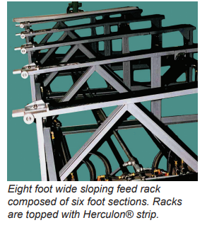
Feed Racks
MAC feed racks consist of a series of welded steel sections braced to accept a standard bundle of material. The racks are usually topped with a 3/4” strip of Herculon®, ultra high molecular weight polyethylene to provide long wear and prevent marking.
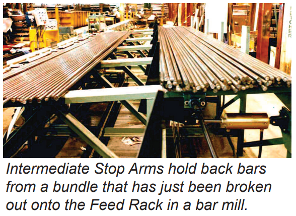
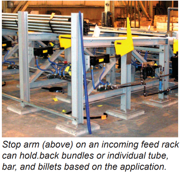
Intermediate Stop Arms
Stop Arms can be installed part way up the feed rack to hold back part of the material, or allow bundles to be broken. The arm is placed in the full "up" position when a bundle of material is placed on the Feed Rack. They are then lowered gradually (controlled by an electrically operated air valve) to allow a limited number of bars or tubes to spread out on the Feed Racks.
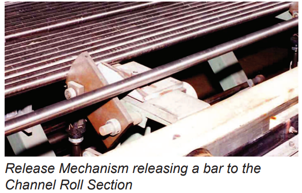
Pneumatic Release Mechanisms
The bars or tubes slide down the feed rack and the release mechanism holds them back and releases them one piece at a time onto the Channel Roll Sections
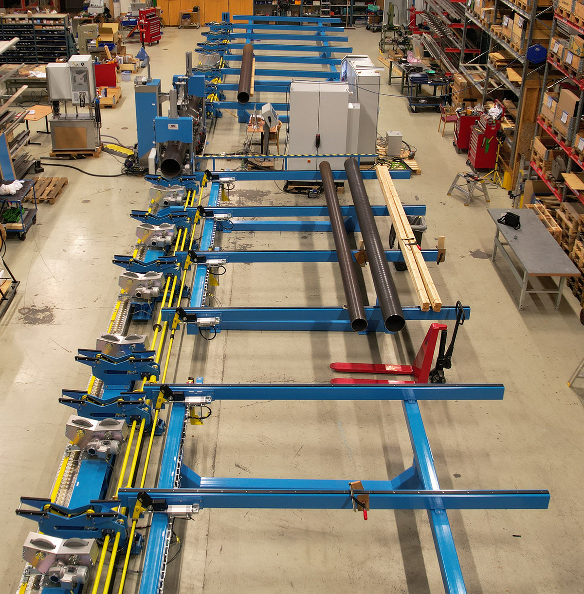
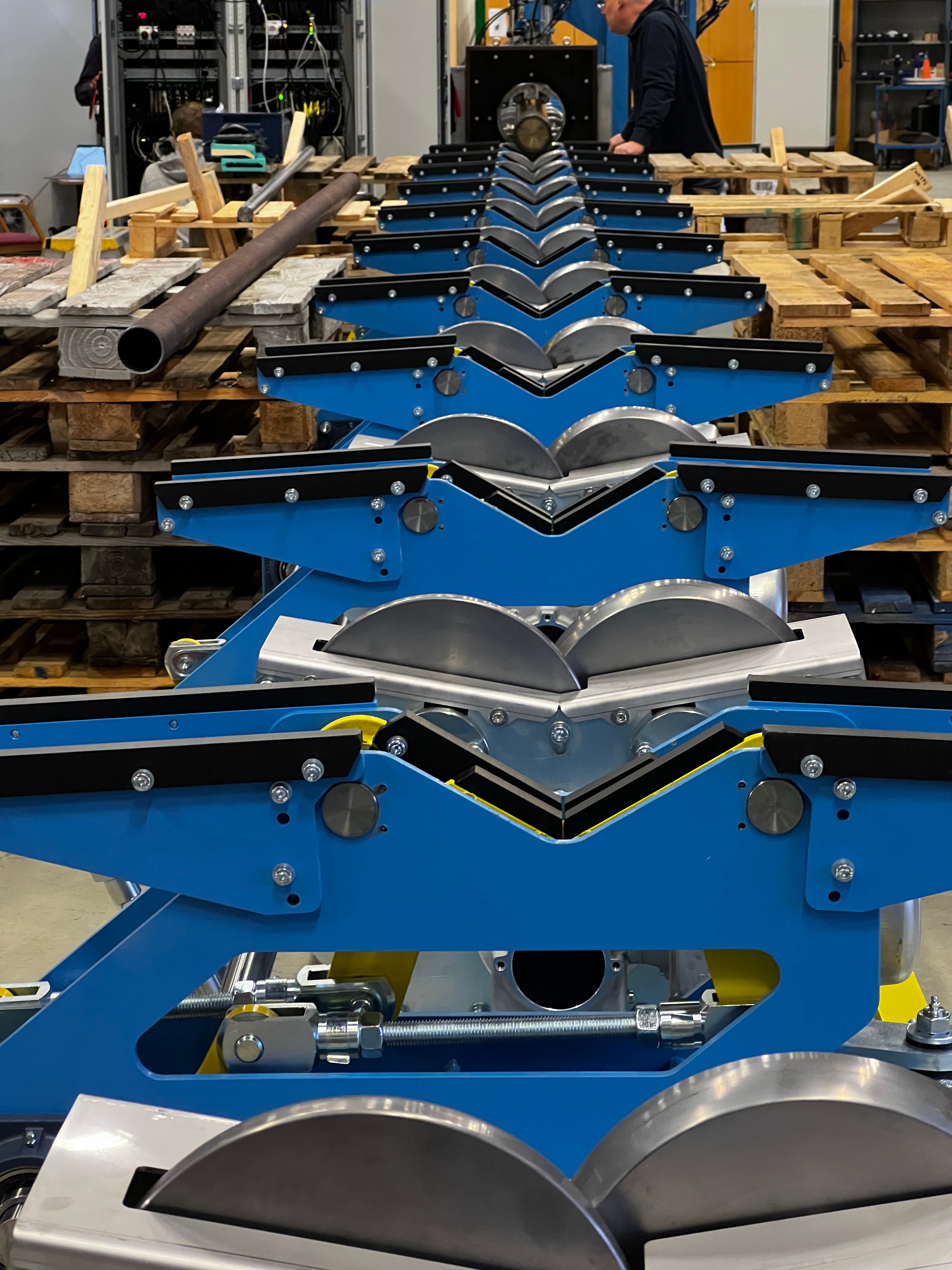
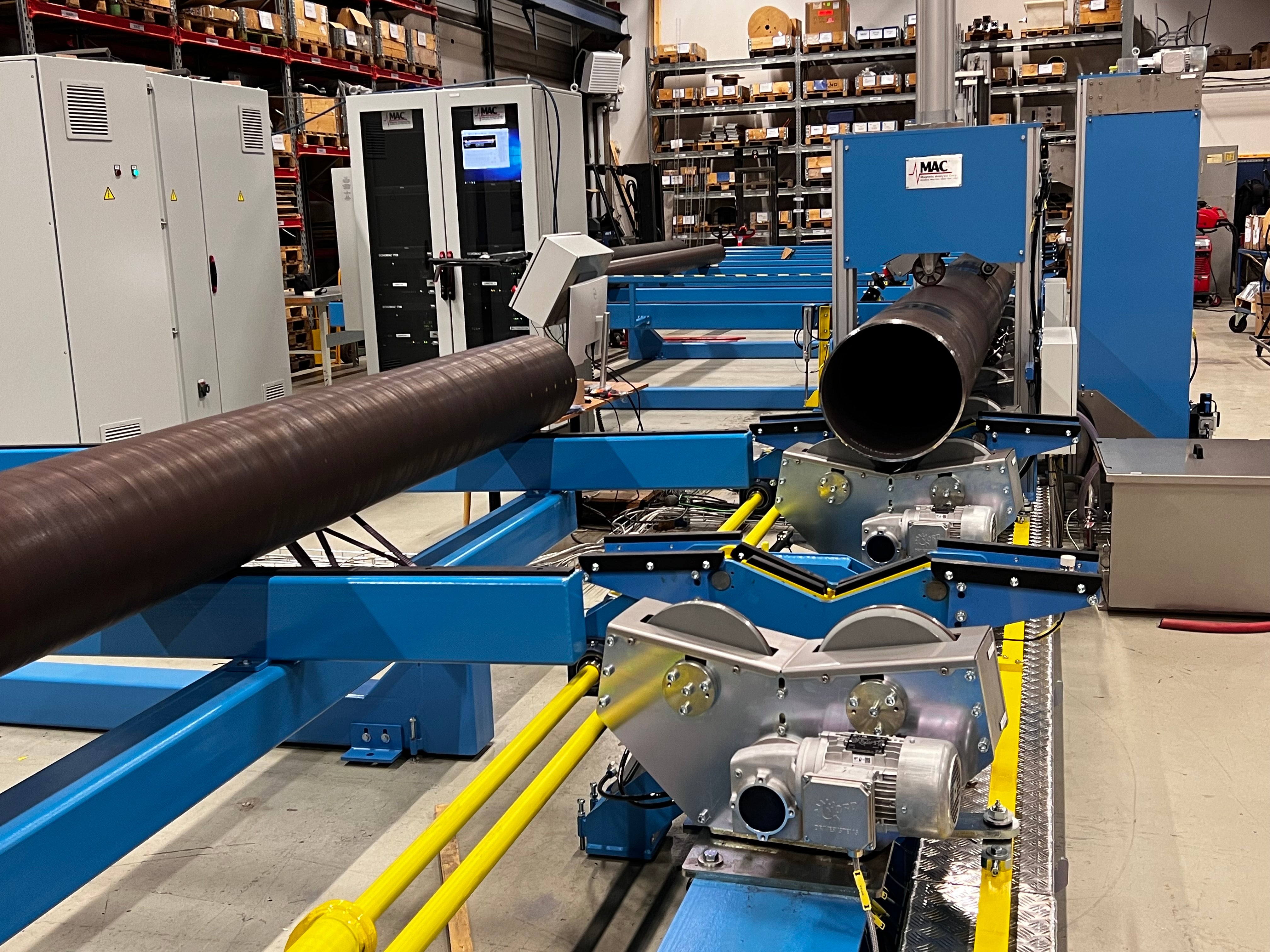
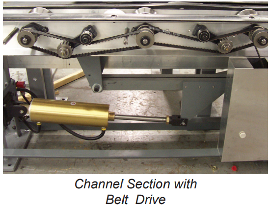
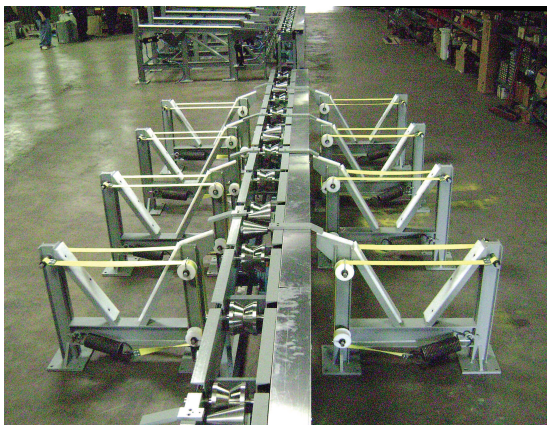
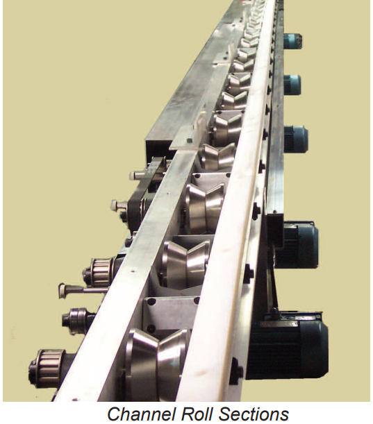
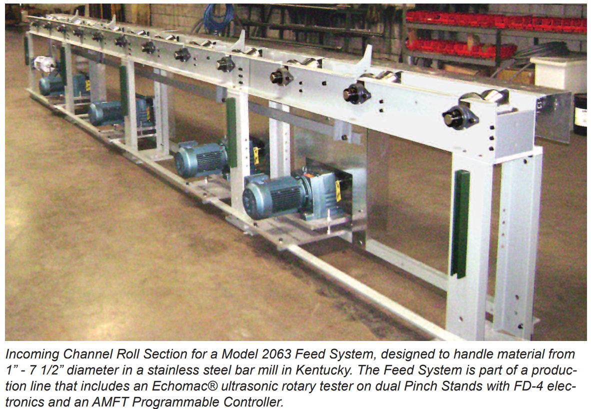
Channel Roll Sections
Six foot long (1. 89m) Channel Roll sections, each with a series of 120° "V" rolls, provide the basic unit for feeding the material to and from the tester. Each roll is individually adjustable for vertical and horizontal displacement to allow exact alignment of all the rolls with respect to each other. Rolls are available in urethane, steel, or hardened steel, depending on the application. Rolls are belt or chain driven, and protective covers are included.
The Channel Roll sections interlock to form a continuous table, supported by Base Units installed at the point of interlock and affixed to the floor. A minimum of two channel roll sections are needed for the input and two for the output. The design ensures more than adequate load bearing capacity and rigidity for the application.
Easy Drop Release
The "Easy-Drop" attachments are mounted between rolls in the incoming channel sections. Separate controls are used to gently move the bar or other material from the Feed Rack onto the V rolls in the Channel Sections. This prevents undue wear and misalignment of the rolls when heavy material is being handled. The mechanism consists of a padded V section which catches the bar when initially released, and then folds downward to place the bar on the moving V rolls.
Throw-Off Attachments
Throw -Off attachments may be mounted between any two rolls in a Channel Roll section. They consist of two cone-shaped rollers, which are activated independently to throw material in the correct direction. The number of Throw-Off attachments used depends on the length of the material being handled. The Throw-Offs are activated by air cylinders which are controlled by the AMFT or PLC which receives signals from the tester's automatic controls.
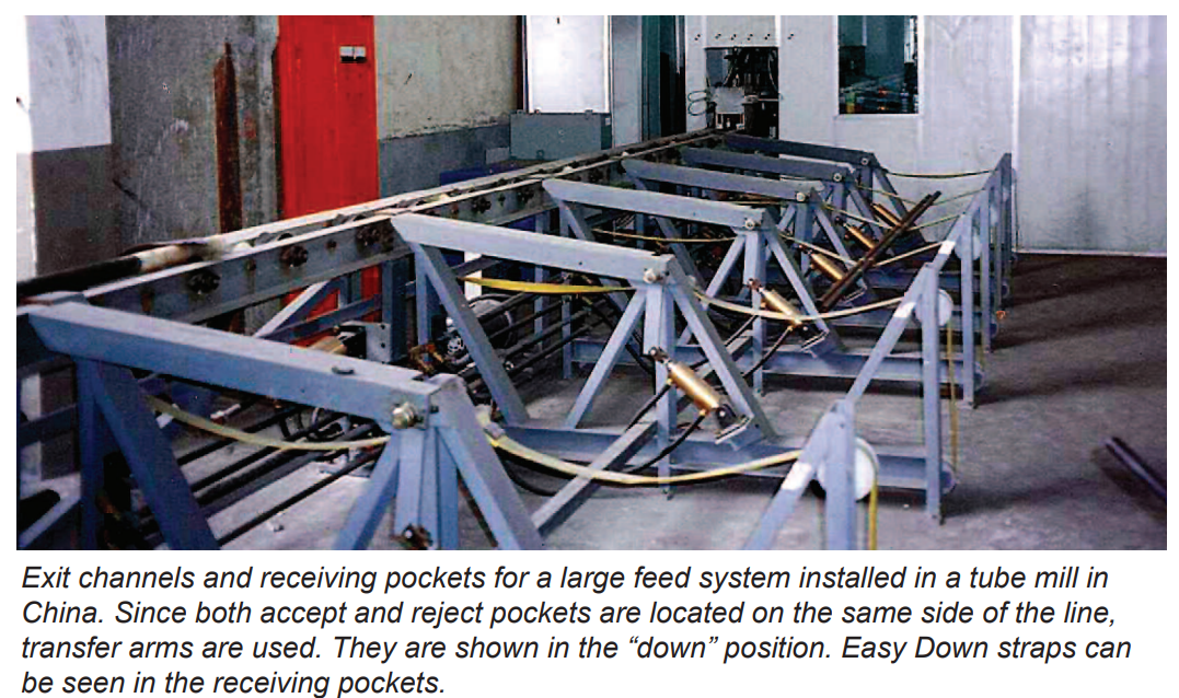
Transfer Arms
Transfer arms are used where receiving pockets can only be positioned on one side of the line. They lift to permit material to be dropped in the accept/reject pocket, when called for by the instrumentation.
Receiving Pockets
Receiving Pockets are used to accept material ejected from the exit Channel Roll Sections. They are made of welded steel channel and can be provided with or without "easy down" hardware to reduce the noise and impact when material is dropped into an empty or partially filled pocket.
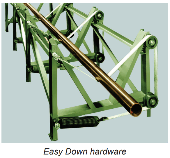
Easy Down Hardware
The Easy Down Hardware consists of high strength nylon straps attached to heavy duty springs. The springs are available in three tension strengths to match the anticipated load in the pocket.
Motor Assemblies
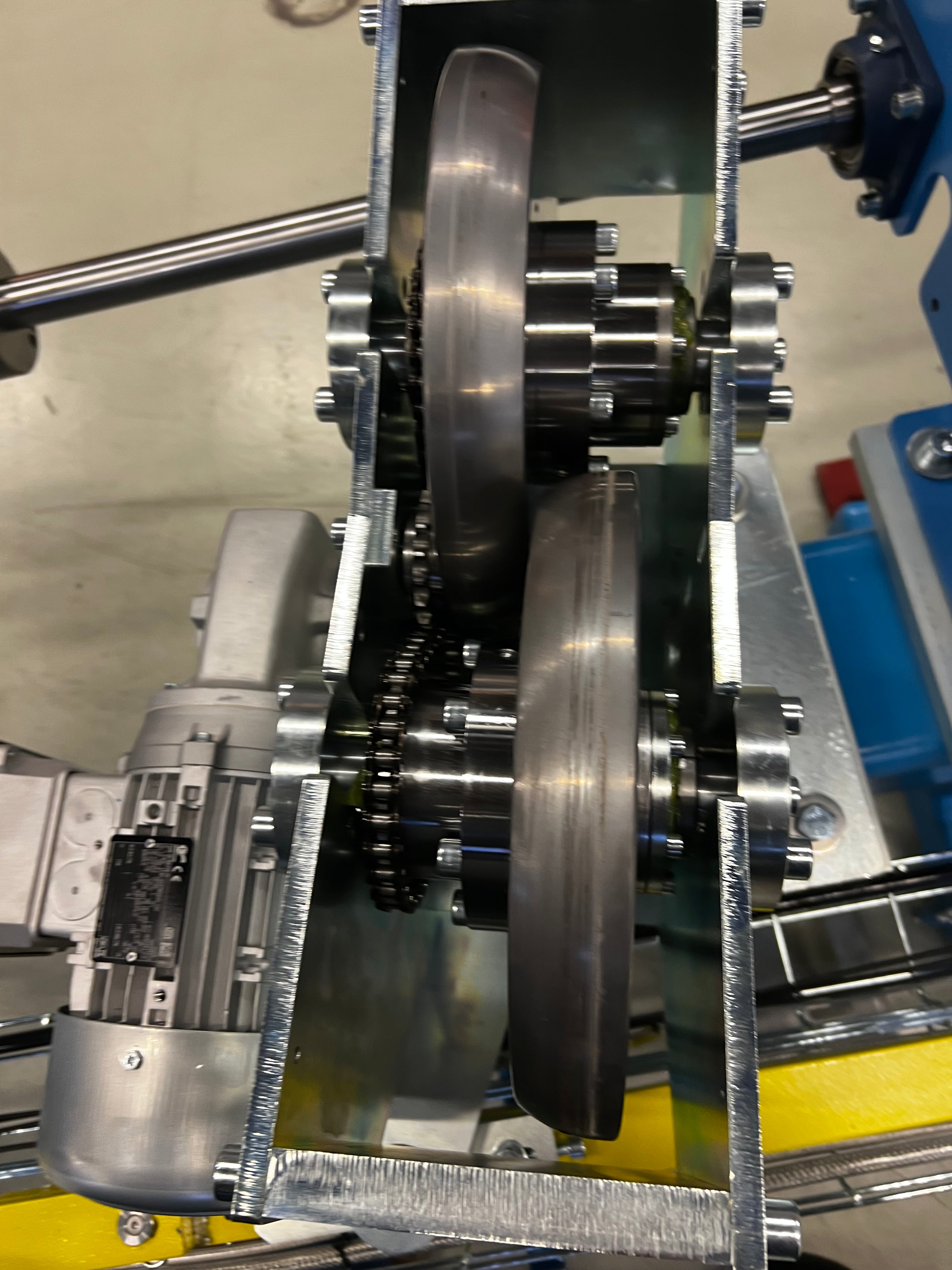
Controlled belt or chain drive motor assemblies are utilized to provide drive power to the Channel Roll Sections. Belt drives are the preferred drive as they are generally quieter and require less maintenance than chain drives. The number and horsepower of the motors is determined by the weight and length of the material being driven.
Motor Assemblies are packaged combinations of motor(s), gear reducer(s), an A/C Frequency Controller to adjust speed, pushbutton forward/off/reverse switch, main disconnect switch, and suitable tensioners and guards.
Motor Assemblies usually include up to four motors, rated 1, 2, 3, or 5HP, with two speed ranges, providing test speeds up to about 250 fpm in the low range, and up to about 600 fpm in the high range. Speed can be varied in all motors simultaneously over an approximate range of 8: 1.
Electrical service must be 3 phase, 460 Volts. Motor Assemblies for other input power are available, at a small additional cost, if specified at time of order. Drawings are available upon request.
AMFT/ PLC Programmable Controller
The Automatic/Manual Feed and Throw-Off programmable controller (AMFT) provides automatic, or automatic/manual, operation of the feed system. In the manual mode, the AMFT provides for push button release of the bar or tube from the Feed Rack to the Channel Roll section, and throw-off in either direction.
In the automatic mode, the AMFT sensors or switches determine when material is in the tester and maintain the release mechanisms and throw-off rolls in the "down" position. When the material leaves the tester, the appropriate set of throw-off rolls and release mechanisms are raised to direct the piece into the correct receiving pocket, and to release the next piece onto the incoming Channel Roll section. As the next piece enters the tester, the release mechanism resets and the "throw-off" rolls return to the "down" position
Test data is used to preset appropriate inputs and outputs to the AMFT so that the correct set of "throw-off" rolls are raised. The Programmable Logic Controller (PLC) is designed for multiple inputs and output arrangements, extended temperature ranges, immunity to electrical noise, and resistance to vibration and impact.
Conductor Control System
The Conductor Control System is an independent computer with interfaces and software to allow the control of multiple test instruments and pinches and to interface between the test line and plant network.
When used to control a test bench, all parameters can be set, stored, and when a new dimension/test is at hand, the computer loads all information to the test electronics, changes all mechanical settings and electronics testing parameters automatically. Only adjustment of sensors must be done manually
The computer is simple with logical menu structures. If an AMFT/ PLC is being used to control mechanics it too can be given instructions through the Conductor computer.
Feed System Specifications
| Model # | 63 | 1063 | 2063 |
|---|---|---|---|
| Size Range of Material (1) | 1/8” - 1 - 1/2” (3.175mm - 38.1mm) | 3/4” - 3 - 1/2” (19.05mm - 88.9mm) | 1.0” - 7 1/2” (25.4mm - 190.5mm) |
| Channel | 4” (101.6mm) wide, Aluminum | 6” (152.4mm) wide, Aluminum | 8” (203.2mm) wide, Steel |
| Roll Size | 4 1/16” dia. x 1 1/4” wide (105mm x 31mm) | 5 1/8” dia x 3 1/8” wide (129mm x 79mm) or 5 3/8” dia x 3” wide (137mm x 76mm) | 6 5/8” dia x 5” wide (168mm x 127mm) |
| Roll Material | Urethane, Steel, or Hardened Steel | Urethane, Steel, or Hardened Steel | Urethane, Steel, or Hardened Steel |
| Channel Sections | 6’ Long (1.8m) | 6’ Long (1.8m) | 6’ Long (1.8m) |
| Rolls Per Section | 3-6 | 2-4 | 2-4 |
| Standard Height (2) | 33 3/64” (839.39mm) | 35 3/4” (908.05mm) | 35 3/4” (908.05mm) |
| Feed Tables | 4’ 6” or 8’ (1.2m, 1.8m, 2.4m) Flat or Sloping | 4’ 6” or 8’ (1.2m, 1.8m, 2.4m) Flat or Sloping | 4’ 6” or 8’ (1.2m, 1.8m, 2.4m) Flat or Sloping |
- When determining the Model to select, the weight and finish of the material being handled as well as the diameter must be taken into consideration. For example, hot rolled 3 1/2” (89.9mm) diameter steel bars would probably require the 2063 Model rather than the 1063.
- The supporting bases can be designed to a different height to meet the customer's specifications.
- All quotations include a complete engineering drawing of the proposed Feed System.
You may also like
Proper positioning of the test coil with respect to the material being tested is a key ingredient of any eddy current inspection system. T